Considering capacitor parasitics
by Patricio Cohen, Electronic Design Engineer
Not all capacitors are created equal
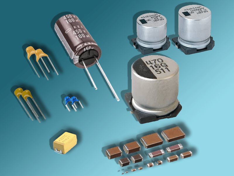
As seen in the picture, there are several types of capacitors that often confuse novice engineers. It’s well known that voltage is a key specification, but is this all that you should take into account? The answer is no, there are other specifications that you should consider as well.
In the market, a wide range of capacitor types is available where each one is more appropriate for certain applications. Electrolytic capacitors have a “can” like “shape” and their use is very common in power circuitry. Their main use is for storing high amounts of energy or for filtering. On the other hand, ceramic and mica capacitors are better for high-frequency applications.
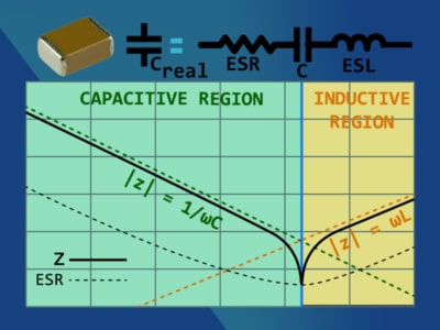
As everything in real life, nothing is ideal and capacitors are no exception. They have parasitics that in some applications you must take into account for achieving the desired performance. The figure shown at the left depicts a model of a real capacitor using ideal passive elements. This series first order model is enough for understanding what happens with the impedance as the frequency increases.
Frequency Response
If we travel the graph shown in the picture starting from the left, we can see that the impedance is first dominated by a capacitive behaviour. This behaviour is due to the capacitance specification alone, which is given by - \frac{1}{\omega C}.
As the frequency increases an impedance minimum occurs at the frequency marked by the blue line that delimits the capacitive and inductive regions. This minimum happens due to the resonance caused by the capacitance and the equivalent series inductance (ESL) and it occurs at the frequency given by: \omega_{r}=\frac{1}{\sqrt {L_{ESL} \cdot C}} or by \large f_{r}=\frac{1}{2 \cdot \pi \sqrt {ESL \cdot C}}. At the resonant frequency, the series combination of the C and the ESL presents zero impedance (short circuit). This means that capacitor’s impedance is equal to the equivalent series resistance or ESR. Then if we continue to increase the frequency we will see that the impedance is clearly dominated by the ESL resulting in an impedance given approx by \large \omega ESL.
Typical values of ESR and ESL
Below is a table showing typical values for ESR and ESL for some types of capacitors just for reference. These values depend on package size, so you must get the exact values from the manufacturer’s datasheet.
| Capacitor type | Capacitance | ESR | ESL |
|---|---|---|---|
| Standard aluminum | 22 µF | 7 Ω – 30 Ω | N/A |
| Standard aluminum | 100 µF | 2 Ω – 7 Ω | N/A |
| Standard aluminum | 470 µF | 130 mΩ – 1500 mΩ | N/A |
| Low-ESR aluminum | 22 µF | 1 Ω – 5 Ω | N/A |
| Low-ESR aluminum | 100 µF | 300 mΩ – 1600 mΩ | N/A |
| Ceramic | 22 µF | less than 15 mΩ | 450 pH – 1.9 nH |
The use of Electrolytic capacitors is mainly in power circuits and in low frequency applications. So for this type of caps ESL is not something to worry about. On the other hand, ESR is very important. This is because it makes the capacitor to dissipate power (heat) which can be fatal if not considered.
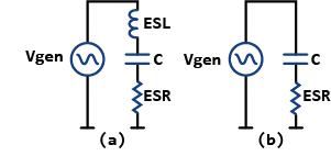
Let’s see the image shown on the right and assume that the signal frequency is well below the resonant frequency. So, the circuit in (b) for this case is equivalent to the circuit in (a). Of course, this is considering the inductive effect to be negligible. Now what happens if the ESR value increases? Yes, the voltage across ESR will increase and this means that power dissipation will be greater. The power dissipation of the ESR is \large P_{ESR}=\frac{{V_{ESR}}^2}{ESR} .
How to destroy a capacitor?
Now you can see that there are 2 ways of destroying a capacitor. The first one is by applying a voltage to its terminals higher than the maximum in the datasheet. And the second one is by applying a very high frequency. Yes, a frequency high enough so that the power dissipation is greater than what the physical package can withstand. This happens because when increasing the frequency, the voltage drop across the ESR will also increase. When reaching the resonant frequency, the signal generator voltage will be completely in parallel with ESR, which is the worst case scenario.
In the latter example, the voltage could be well below its maximum recommended value. The maximum current that can pass safely through the capacitor is commonly known as ripple current in datasheets. Currents greater than the maximum ripple current rating will generate an excessive power dissipation in the package. This, in the end, will damage the capacitor. Also, the ESR will affect the ripple voltage seen at the output of power converters. That is why choosing low ESR capacitors is very important for achieving a good performance in switched mode power supplies.
Rail collapse in Power Integrity
Let’s see another example related to this topic. Do you know what happens when choosing the incorrect capacitors for the PDN of a high-speed digital system? PDN is an acronym for Power Delivery Network.
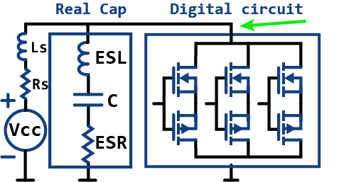
Let’s consider the circuit shown on the right. The Vcc voltage source in series with Rs and Ls is the model for the output of a power supply or voltage regulator module (VRM). The MOSFETS are modeling 3 typical output buffers that could be part of a microcontroller or ASIC in a PCB. When the MOSFETS switch at very high frequencies, they are trying to sink very high frequency currents from the power supply. But, since VRMs provide DC power, they are not good for supplying fast transient currents and the voltage rail drops. The name for this phenomenon is “rail collapse” and is a very common topic in the Signal and Power integrity arena.
Effect of adding several decoupling capacitors in parallel
When you add decoupling capacitors in parallel to the VRM’s output, what you are basically doing is to put a small voltage supply capable of delivering fast currents to a load. Because the capacitance of these small voltage supplies is usually not high, it is necessary to put several in parallel. This is, to have enough “high frequency energy” stored for delivery in form of fast currents.
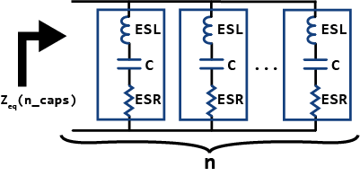
If we look at the picture on the right, we can understand easily why it is a good idea to put several capacitors in parallel. Since the impedance of a single capacitor is \large Z_{CAP}=ESR+j \omega \cdot ESL + \frac {-j}{\omega C}, the impedance of n equal capacitors in parallel is:
\large Z_{eq}(n_{CAPS})=\frac {ESR}{n} + j \omega \cdot \frac{ESL}{n} + \frac {-j}{\omega C \cdot n}
What this last equation is showing is that if you connect n capacitors in parallel, the ESR and ESL gets divided by n and C is multiplied by n, just what we need. So this resultant capacitor is a lot better than a single one, not only because it has n times more capacitance, but also because we have a reduction of n times in their parasitics as well.
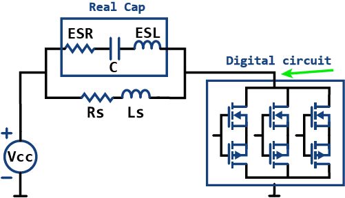
If we go back 2 figures and get the Thévenin equivalent circuit of the voltage source including its parasitics and the real capacitor you will see the equivalent circuit shown on the left. Now the parallel between the voltage supply’s series impedance and the real capacitor series impedance is the Thévenin equivalent series impedance. The Thévenin series impedance is the effective impedance of the power delivery system. If we add more capacitors in parallel this Thévenin impedance will decrease,. In other words you could see this as lowering the power delivery series impedance which is improving the power supply’s frequency response.
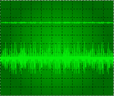
What rail collapse looks like?
If you use inappropriate capacitors, the voltage rail will not be able to supply those currents and rail collapse will happen.
Because high-speed digital signals may be well into the gigahertz range, the ESR and ESL are now important for specifying the frequency characteristics of a capacitor. ESL is highly dependent on the package size, so smaller caps are a better alternative for decoupling. Also, the PCB layout plays a fundamental role. Routing adds resistance and inductance to the circuit and could mask the performance of a good capacitor. This is why you should place capacitors very close to integrated circuits and lots in parallel.
In the figure shown on the right, you can see an oscilloscope screenshot showing two ac coupled channels. Both are showing the voltage rail of a circuit, the top for a correctly designed power delivery network and the bottom for a poor one. All that noise shown in the bottom channel is due to the rail collapsing. Or in other words, the PDN is not capable of delivering the necessary current in the necessary amount of time. This, of course, produces several problems digital systems in general. Microprocessors and ASICS can get in a blocked state or perform unpredicted actions when the voltage drops. Also, lots of radiation will generate from the PDN, producing electromagnetic compatibility issues.
Conclusion
In real-world applications, engineers almost always connect more than one type of capacitor to the power delivery network. This is because with different capacitor values you can have a low impedance for all the working frequency range. So, when this happens \large Z_{eq} is a much complex expression where multiple resonances will be present. Therefore, that is why is important to use a Power Integrity software package for an accurate prediction. However, for academic purposes using the same capacitor multiple times is enough for explaining the idea.

